

Evolution of BMW Intake Designs
- Jun 11, 2020
- 14 min read
Updated: May 20, 2021
Internal combustion engines are air pumps and how much power they make is determined mostly by how much air they can get into the cylinders during each intake stroke. How much air the cylinders can intake is determined in large part by the intake design and BMW intake systems have historically featured some very advanced technology, in this article I will go into some detail on what sets BMW intakes apart and the evolution of BMW intake systems from the vintage period up until the modern turbocharged era. Forced induction motors have much different intake design considerations than naturally aspirated motors so I will cover those in a later article
I want to try to make this information approachable to anyone with a basic understanding of engines. Lets start with a basic review of how an engine operates, below is labelled cutaway diagram of an engine

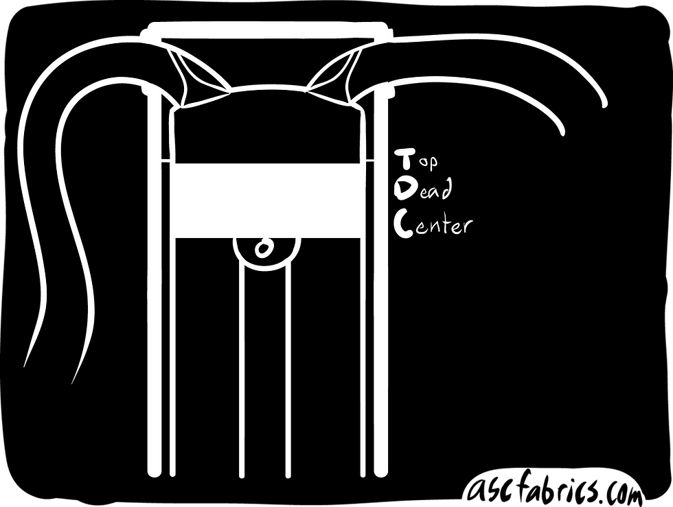
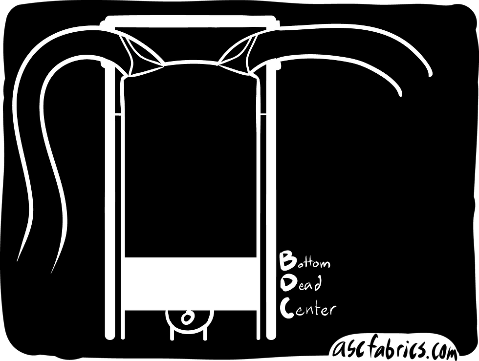
Top Dead Center, shown above, represents the top-most point of the piston's travel. Conversely, Bottom Dead Center, shown below, represents the bottom-most point of the piston's travel
The piston moves up and down in the sealed cylinder chamber and there are four steps or "strokes" to a typical automotive combustion engine
Intake Stroke - with the piston starting at TDC, the intake valve opens as the piston travels down, the piston's downward movement creates a vacuum which draws air (which is pre-mixed with fuel in port injection or carbureted engines) into the cylinder
Compression Stroke - the intake valve closes and the piston moves upwards, compressing the air/fuel mixture until the piston reaches TDC (at this point, in a direct injection engine, the fuel injector will spray fuel)
Power Stroke - a spark plug ignites the compressed air fuel mixture, combusting it. The force of the expansion from the combustion forces the piston down which rotates the crankshaft (not pictured), thus generating torque
Exhaust stroke - the exhaust valve opens after the piston reaches BDC and as the piston moves upwards it forces the exhaust gas out of the cylinder, ready to restart the cycle and take in fresh air on the next cycle
This process looks like the below .gif

Now, now that we understand how an engine operates lets take a step back...
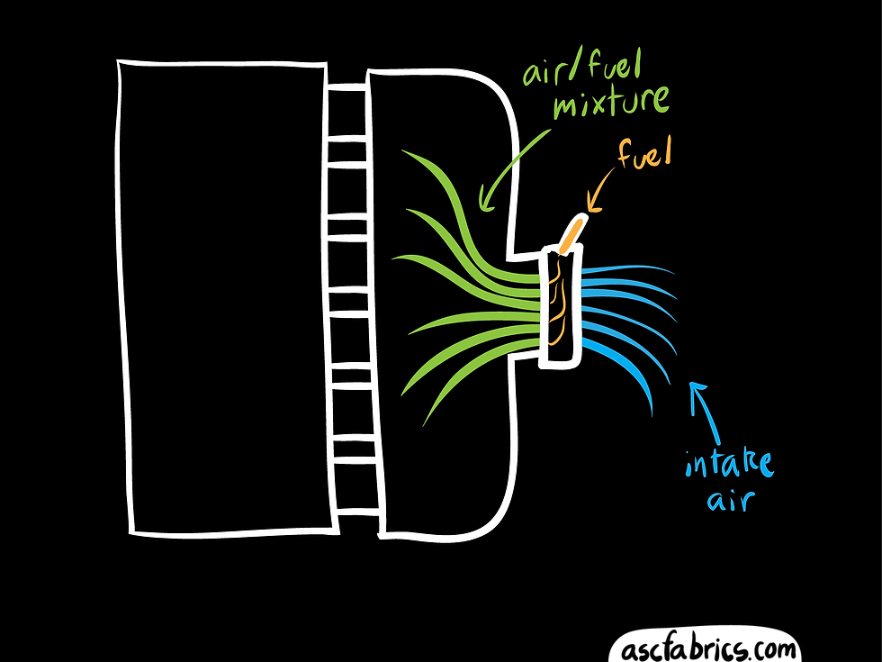
Up until the early '80s, most BMW's were carbureted. This meant that a carburetor supplied fuel at the throttle plate into the intake at a set rate depending on throttle position. The intake air (blue) mixes with the fuel (yellow) and the air/fuel mixture (green) reaches the cylinders
Carbureted intake designs are not ideal for a few reasons - the main reason is that it is difficult to control the exact amount of air/fuel mixture going into each cylinder. There is also perceptible throttle lag with these setups. Throttle lag is a delay between pressing the throttle and the engine responding, in this case it is caused by the manifold being under vacuum, this phenomena is talked about more in depth later in the article. For now, it is most important to understand that throttle lag increases as you increase the distance or intake volume between cylinder and throttle body
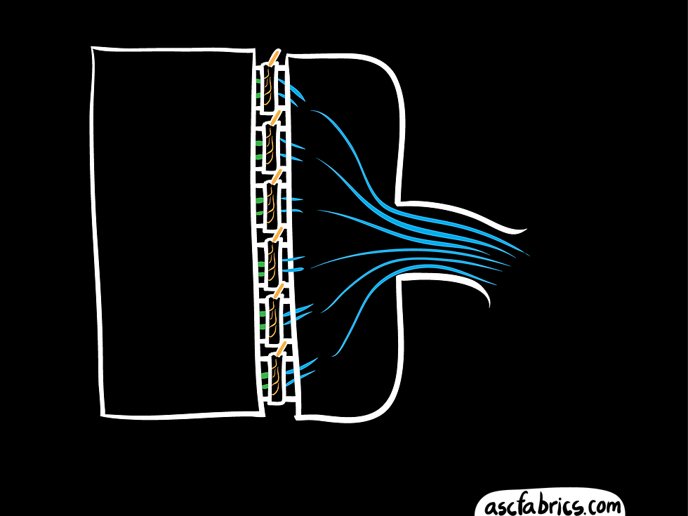
Both those issues can be somewhat alleviated with the use of more carburetors. The more carbs you have, the shorter the distance to the cylinder from the throttle (and thus less throttle lag) and you also gain more precise control over the specific amount of fuel making it to each cylinder. Below is a configuration with six carbs, however most multiple carb setups ran multiple cylinders off one carb, like the M30 six cylinder engine which had dual carburetors with each one feeding three cylinders
A lot of the technology around carbureted engines went into combustion chamber design and improvements to the jets (jets are basically what injectors are called on carburetors) in order to increase atomization of the fuel as it was being injected. Finer atomization of the fuel means a more homogeneous mix of the air/fuel mixture which leads to better combustion. An interesting feature from this era, the M30 featured a triple hemispheric combustion chamber design. The goal of introducing this design into the head is so that as the engine is on the compression stroke and the air/fuel mixture is forced upwards, it enters the hemispheric chamber in the head which causes a swirling action which promotes greater mixing of the air and fuel, as a more homogenous air/fuel mixture burns more efficiently than a less well mixed air/fuel charge
This setup is still not ideal though as the amount of fuel entering the cylinders is directly proportional to the throttle position and this does not account for other factors which can affect the engine's combustion efficiency. Adding more carbs also introduces more expense and complexity
The automotive industry as a whole therefore moved from fuel supply systems which were carbureted to the more modern fuel injection. With fuel injection systems, the fuel is injected much closer to the cylinder. This allows for increased performance and efficiency as only the fuel required for combustion is injected into the engine. Fuel injection setups also allow for variable amounts of fuel to be injected depending on the combustion efficiency, which is measured with O2 sensors in the exhaust. This allows fuel injected engines to achieve good power figures while still getting reasonable fuel efficiency when cruising. Below we see a traditional throttle body setup, with the throttle body mounted at the entry point of the intake manifold and a mass airflow sensor upstream from that
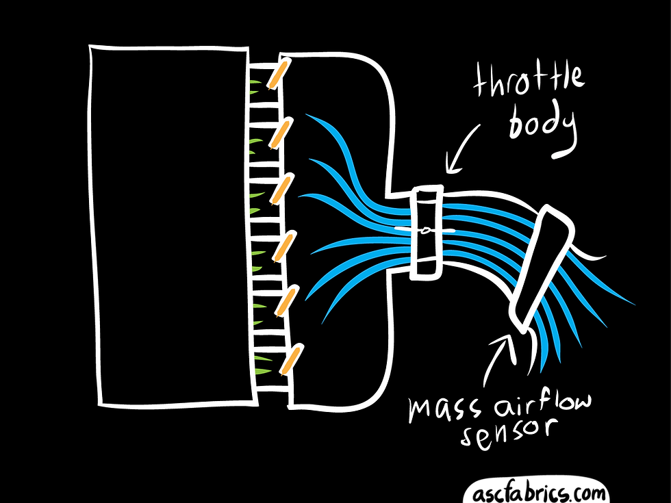
The mass airflow sensor provides data to an engine computer to determine how much air is entering the engine. The engine compares the data from this sensor to the oxygen sensor in the exhaust in order to determine how efficient the combustion is and adjust fueling accordingly. This allows the engine to maintain as close to the ideal combustion ratio as possible under varying driving circumstances. However this type of intake design provides relatively poor throttle response due to the distance from throttle plate to the cylinders and because the manifold will remain under vacuum at part throttle until the throttle is opened
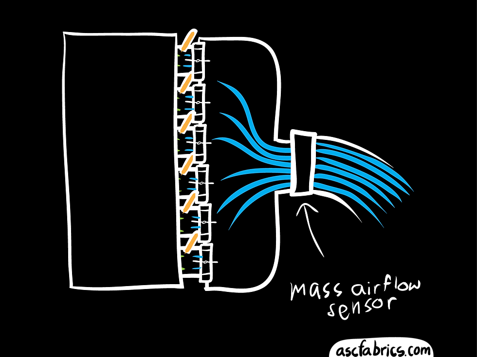
An age-old solution to this problem is similar to what we looked at above with the additional carbs and that is individual throttle bodies or ITB's. Engines with ITB's have the throttle bodies placed directly in front of each cylinder. This allows for very fast throttle response as the air in the manifold will already be at an equalized pressure and because the throttle plate is located very close to the cylinder there is less distance from throttle plate to cylinder. ITB's were a staple of naturally aspirated BMW M series engines from their inception until they went to turbo engines in the 2010's. However, despite not using ITB's the modern M turbo engines did not sacrifice much in the way of throttle response due to another technology I will talk about later. Below we see a six cylinder engine with six individual throttle bodies, similar to a euro S50 or S54
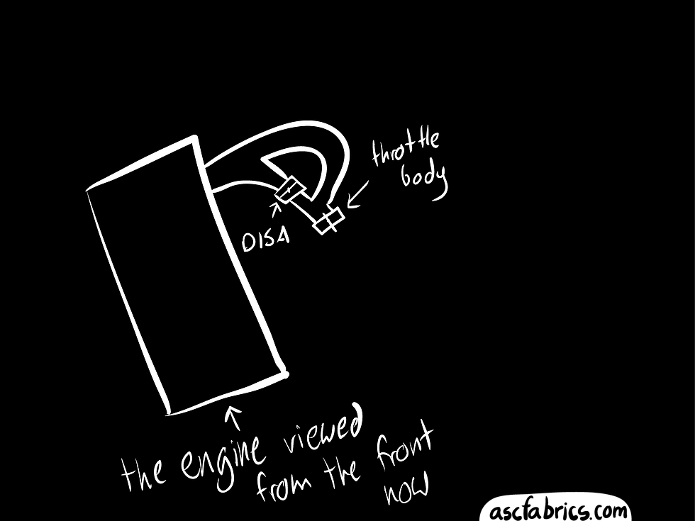
ITB's are a great design with minimal performance compromises but were cost prohibitive for non-M engines, so BMW continued to develop the traditional style intake manifold, culminating in the DISA resonance manifold. The DISA resonance manifold features two sets of intake runners for each cylinder and uses an electronically controlled flap to control which path the air follows. The first use of this technology on a BMW engine was the M44 although most in the US are probably more familiar with it in the six cylinder applications that followed: notably the M52TU and M54. This technology allows for the benefits of both a short intake runner manifold and a longer intake runner manifold and also takes advantage of resonance waves in the intake manifold in order to boost power. A later evolution of this technology featured a three-stage DISA, with three different length intake runners, as featured on the N52. An illustration of the more popular two-stage DISA intake is below
Below is a .gif illustrating the operating of the DISA intake. At higher RPM's the DISA flap opens, allowing air to reach the cylinder through an additional shorter path, which helps cylinder filling at high rpm, increasing top end power
So this might raise the question - why have a longer intake path at all - why does that help the powerband? Why not just have have a huge, very open intake manifold with as much volume as possible? One answer to this is in an often overlooked benefit of the DISA, which is improved throttle response
At part throttle, like when cruising on the highway, the engine wants to use as little fuel as possible. So to maintain the correct air/fuel ratio, the throttle body is not fully open (its almost closed, in fact) in order to limit air consumption and therefore limit fuel consumption. But the valves are still opening and the pistons are still creating vacuum in the cylinders, this results in the engine creating vacuum in the intake manifold since it is pumping all of the air out of the intake - the throttle body is open only just enough to let in the bare minimum amount of air required. If you give it throttle from this partial load state, it takes a moment for the intake manifold to fill with air since it was under partial vacuum, this delay results in a moment in which the throttle is open but the cylinders do not have an adequate supply of air - this is perceived as throttle lag. The larger the intake manifold, the longer it takes for pressure to equalize and the more lag there is. Even on race cars, manifolds must be designed with this in mind since cars go from on throttle to off throttle when braking or turning and lag during this switch is not ideal.
To minimize the compromise inherent in this single throttle body design, the DISA flap serves to split the intake manifold into two sections of three cylinders, which means the air only has to equalize over roughly half the volume as it would otherwise have to before it reaches a cylinder, which improves throttle response
An important thing to note here is that this vacuum only occurs between the throttle body and cylinder - on motors with a single throttle body, this means the intake manifold is under vacuum. On motors with individual throttle bodies, since they are mounted at the engine head, there is only a very small vacuum formed between each throttle body and the cylinder. This leads to an almost imperceptible amount of throttle lag since a large volume of air is immediately and plentifully available in the intake plenum
However, there is a second, much more interesting and important function of the DISA. And that is the separation of the resonance chamber. The resonance intake is a simple design in theory but one that takes a lot of precision engineering and fine tuning
An overview of how this works is below
1. Air is pulled into the intake manifold due to the vacuum created in the cylinder, creating a wave of air rushing towards the cylinder to fill the vacuum
2. As the intake valve closes this high velocity air hits the back of the intake valve, forming a pressure wave which reflects back into the intake manifold
3. If designed properly, this pressure wave will hit the next intake valve when it is open (and ideally just before it closes) - forcing a little extra air into the cylinder
Note in the below diagram it looks like a 2 cylinder engine - it's a 6 cylinder I just didn't draw all the runners. On the 6 cylinder engines, due to the firing order (1-5-3-6-2-4), the intake valve which opens next will always appear on the opposite 3 cylinders of the engine from the one that just closed. The M44 firing order is different (1-3-4-2) and required pairing cylinder 1 with 4 and 2 with 3 in order to maximize this resonance effect. Below is a simple representation of a 6 cylinder DISA resonance intake, as seen on M52TU, M54 and N52 engines
At low engine speeds, there is a longer delay between when the intake valves are open so the runners are longer in order to delay the movement of the pressure wave

At faster engine speeds the intake valves are opening more quickly in relation to one another, meaning you want a shorter distance in order to have the pressure wave hit the intake valve at the right time
Historically, intake manifolds were a compromised design - they could be designed to boost low-end torque with longer runner lengths, or help horsepower at the expense of low-end torque with shorter runner lengths
The DISA resonance manifold provides the benefits of both short and longer runner lengths as well as an improvement in throttle response and this resonance intake effect. Let us look at a dyno graph for a minute because who doesn't love dyno graphs?
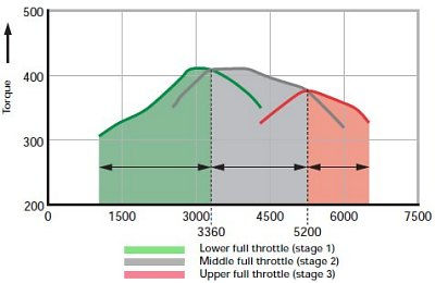
The above image is from an Autozine article about, you guessed it, Variable Length Intake Manifolds. It is great further reading if you are interested in this topic, link here
In the above image we see a dyno, on which three dyno graphs are actually present. The green dyno line indicates an intake with long intake runners, the red line one with short runners and the gray an in-between. Normally long intake runner lengths suffer in the high rpm, as you can see from the green dyno line trending downwards steeply in the higher revs. Conversely, short runners perform poorly at low rpm, which is why the red dyno comes from such a low torque rating at low revs. A three-stage DISA system allows the engine to follow the "peaks" of each dyno, to get the gains of each type of intake length without the associated drawbacks
Now that we understand the basic principles of the intake resonance system I want to talk about exhausts for a minute...
It is important to first understand that the ultimate goal of an exhaust from a performance perspective is to decrease the pressure behind the exhaust valve at the engine head. The reason for this is that the less pressure there is behind the exhaust valve then the more effective the exhaust stroke is at evacuating the exhaust gasses. Less exhaust gas in the cylinder means a larger amount of the cylinder's volume becomes available for the next air/fuel mixture and the less hot gas there is remaining in the cylinder then the cooler the intake charge will be (thus the more it can be compressed before ignition for greater power)
One of the main ways to decrease the pressure at the exhaust valve is via scavenging, which is when the high velocity gas from one cylinder's exhaust pulse draws a vacuum in another cylinder's exhaust pipe as it passes by the merge point. This causes a large decrease in pressure at the exhaust valve for a brief moment. If the exhaust valve is opened right as this vacuum is being created then it results in a slight boost in power over a small rpm range. The length and diameter of the exhaust pipes as well as location of the merge points are tuned to adjust where this effect occurs

I just threw this .gif together really quick because the exhaust section seemed like a boring wall of text. I may improve it at some point
I can't talk about exhausts without talking about the famous b-word. "Backpressure" is a buzzword but what it really means is inefficiency in evacuating exhaust gasses. You do not want backpressure in any form, you want the exhaust to efficiently flow out of the cylinder which is most easily done by making the exhaust flow efficiently out of the exhaust pipes. If the exhaust is too small, it acts as a restriction and the required exhaust volume can not efficiently flow and it causes a blockage. However, that is not to say that you just want a huge exhaust. There is such thing as too big. Exhausts are like Goldilocks or whatever. You don't want them too small, because then you get blockages, but you also don't want them too big, because then you get blockages
Weird, right?
So this is a natural, if not totally forced, segue into talking about exhaust velocity. If your exhaust is too large of a diameter then the exhaust will cool off and slow down in the exhaust and the exhaust gasses themselves become a blockage
Oh and as for why exhaust blockages are bad - it's the same effect as intake resonance: a high pressure exhaust wave is forced out of the cylinder by the piston which travels down the exhaust, if it hits a blockage then a pressure wave bounces off the blockage and travels back up the exhaust, providing that same effect as discussed with the intake resonance. Our goal is low pressure behind the exhaust valve, so a high pressure wave travelling towards your exhaust valve is not ideal
The exhaust velocity at your muffler tip is much lower than that of when it is leaving the cylinder, so no matter what, exhaust velocity will decrease along the length of the exhaust pipe. This occurs without causing a blockage by allowing the exhaust to slow in velocity over a long distance with minimal restrictions. In this way, each exhaust pulse slows down naturally and as each exhaust pulse slows down at the same rate there is no buildup of exhaust pressure. When you increase the engine rpm, a faster exhaust pulse may collide into the back of a slower exhaust pulse, but this should occur far enough downstream from the head that the exhaust pulse has already lost most of it's energy and if tuned correctly, will not be able to reflect back and reach the head. Because exhausts conform to space restrictions and can not flow perfectly without restriction, there also exist some exhaust features which are designed to eliminate or minimize the resultant backwards pressure waves. The most notable of these are resonators, which are designed to deflect these backwards waves into a chamber, where it will bounce around and lose energy, instead of going up the exhaust
Now for a very cool technology... Valvetronic

This diagram should look very familiar, it is essentially the same as the earlier diagrams I drew - this one in particular being almost identical to the design of a fuel injected motor with a single throttle body. Except, as you may observe, there is no throttle body. This is for illustration purposes only - the Valvetronic motors DO have throttle bodies. But, I didn't draw it here because it doesn't really need it's throttle body. In fact, it only actually uses it for low-load operation under certain conditions, it's kind of like an extended idle control valve
The point I'm trying to get at is motors equipped with Valvetronic do not use a throttle body in a traditional sense. In many modes of operation, the throttle body remains completely open. That is the real magic of Valvetronic. It is a system which, dare I say it? Can provide better throttle response than individual throttle bodies. Whaaaaat? So what is Valvetronic? Well - it's all in the name - "Valvetronic" from the latin root "valvae" meaning valve, and the greco-roman "tronic" meaning "adjusts the valve lift to act as a throttle, instead of the throttle body"
That's right, Valvetronic controls valve lift over a huge operating range which allows the intake valve itself to act as a throttle body. Like engines equipped with individual throttle bodies, the intake manifold in engines with Valvetronic operates under ambient pressure, not vacuum. This is why the N52 could utilize a three-stage DISA intake manifold with a relatively large volume while also having improved throttle response over it's predecessor
Also as a small footnote - some engine accessories need vacuum, so all engines equipped with Valvetronic have vacuum pumps to account for this
The N62 is the last naturally aspirated V8 that BMW produced. It was also in my opinion one of the best naturally aspirated V8 engines ever made, right up there with the BMW S62. One of the best parts of the N62 was it's intake manifold which I think is one of the most underappreciated pieces of technology of all time - the DIVA intake or Differentiated Variable Air Intake. This is the only continuously variable length intake manifold ever made for a production engine and even BMW themselves didn't use it for the N62's entire production run, switching to a cheaper to produce and easier to package three-stage DISA intake manifold design for the later year engines. What does that mean - continuously variable length intake? We know from earlier that DISA intakes are variable length, with two (or three) different lengths of runners and we have explored this intake design in length above
But the N62's is continuously variable. It is not two stages, or three stages. If we think back to that dyno graph image earlier, it had three dynos on it and the three stage intake allowed it to follow the peak of each of those. A continuously variable intake length would be as if you plotted an infinite amount of dynos and followed their peaks in order to fully maximize the performance of the engine over the entire rev range. This intake was one of this engine's biggest performance benefits (Valvetronic increased throttle response as well as efficiency but in itself did not do a lot for performance gains) over the previous generation M62, so while we can't possibly create dynos for every possible runner length, BMW themsleves were kind enough to overlay a dyno of the N62 4.4 with the previous generation M62 4.4 and the broadness of the torque curve as well as the horsepower continuing to climb is a direct result of the intake manifold
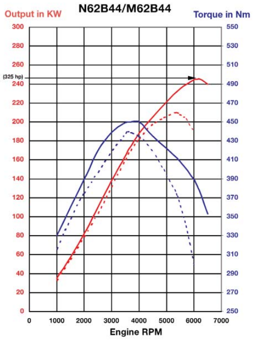
The solid lines represent the N62, dotted lines are the M62
As for how it actually works, it's a rather genius system - the intake runners are mounted around the inside perimeter of a cylindrical intake. A motor at the rear of the intake spins a shaft which rotates the intake runners, allowing the length to vary in length over a huge operating range. It works on a similar principle to the DISA intake, but it does not use a flap - it just varies the length of the intake by rotating them
The turbocharged engines are a story for another day. I do plan on covering them in-depth though - touching on topics like what is a twin scroll, why are they integrating headers into the head, what is the optimal design for a turbocharged intake as far as volume and the reasoning for switching the orientation of the intake and exhaust to make a "hot V" engine where the turbochargers are in the engine valley...


Comments