

N62 Z3 Part 19: Steering Shaft & Power Steering
- Graham

- Aug 14, 2021
- 11 min read
Updated: Oct 25, 2021
Soo previously I thought I could maybe use the stock shaft. Which was 100% wrong haha
With the engine mount in place I started looking at where the routing would be. I want it to be as close to the engine mount as possible and as far from the engine mount arm and exhaust manifold as I can get it. Those parts move - the engine mount won't
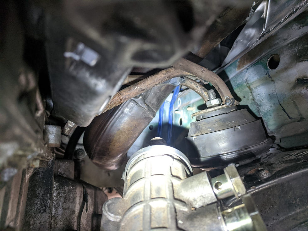
Below is the perspective from the previous image up to the firewall location
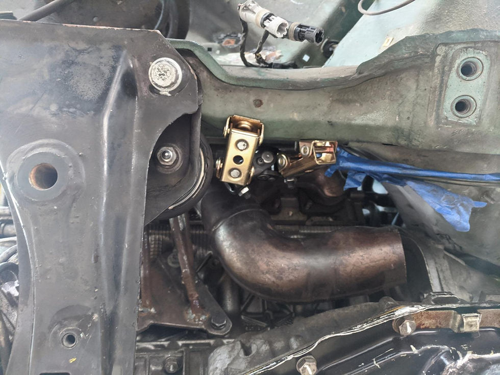
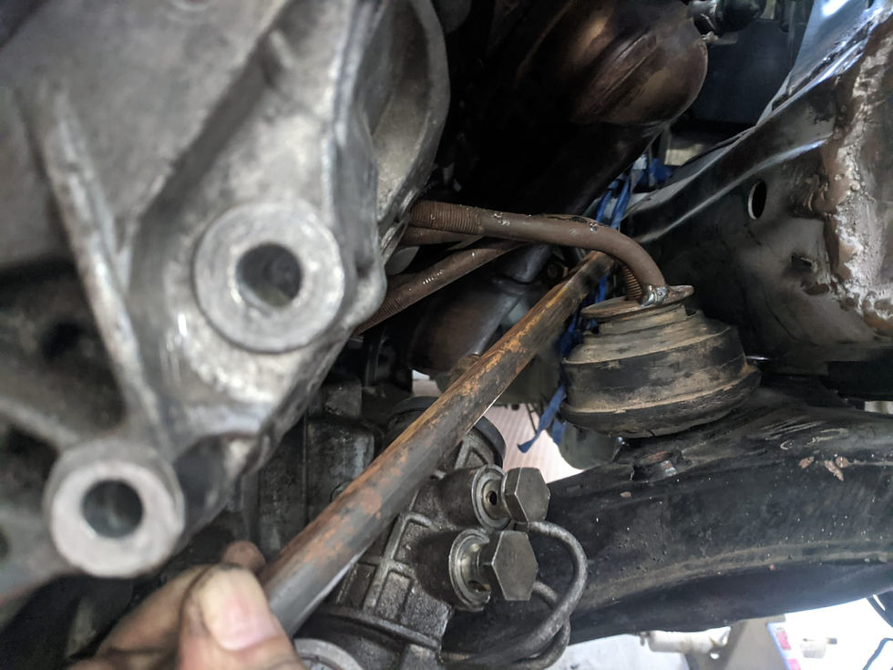
Used some magnets to roughly determine the location of the U-joints and the shaft - this was done in part to see if I could determine the operating angle of the U-joint, to see if I need a double joint, which I miiiight end up needing... it's hard to say right now. The ideal operating angle of these U-joints is 35 degrees or under. The double U-joints go up to 80 degrees. As it is roughly mocked up now, it measures at 42 degrees. The main problem is that as I reduce the angle it will move the shaft towards the engine. I plan on cutting a little bit off the steering rack input shaft, as moving the U-joint location further down the splines will reduce the angle, but I'm not sure it will do so by enough
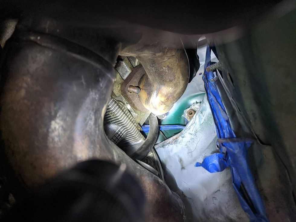
With some extensions showing shaft routing. It's very tight

Perspective from the middle U-joint looking up to the firewall
Have I mentioned how tight things are?
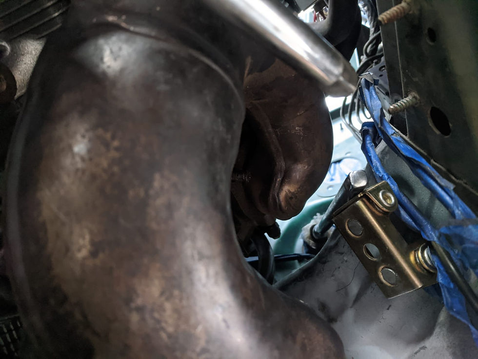
From the firewall looking down

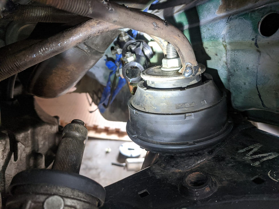
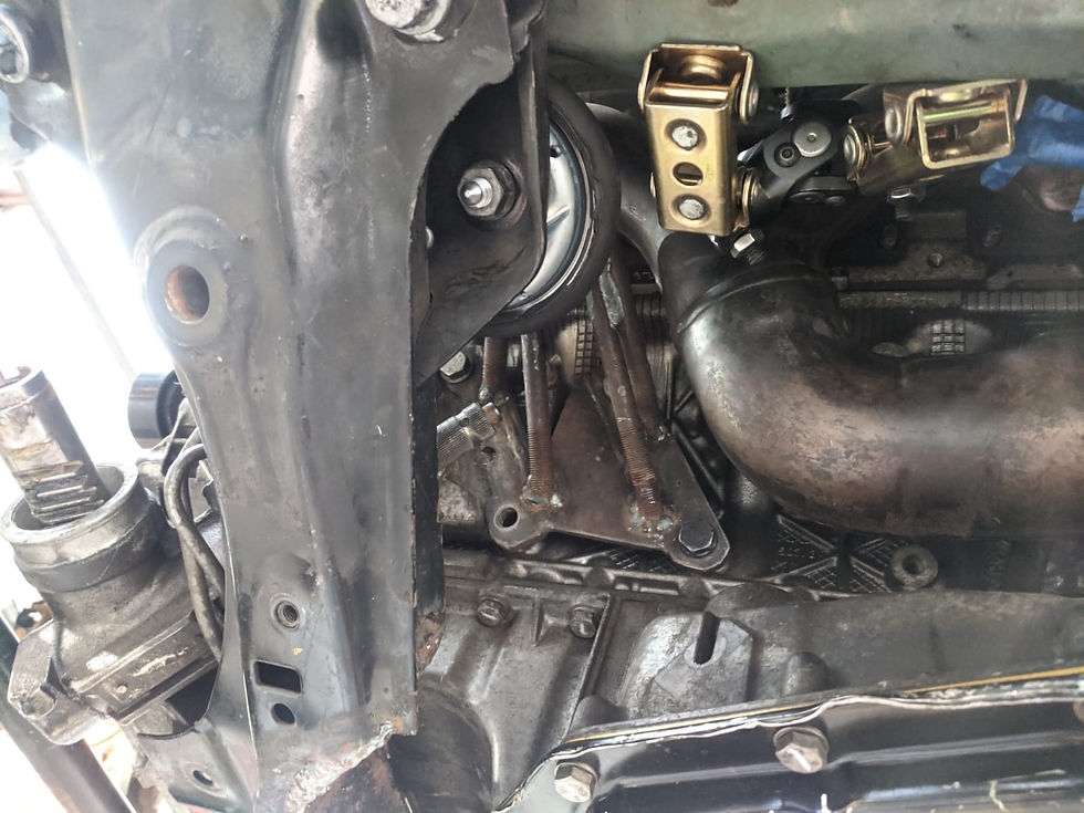
I also did observe that both engine mount arms will be serviceable with the engine fully installed, which is really great. The driver's side may require removing the alternator- if so I am glad I notched the framerail as long as I did so I can remove that with the engine in place!
Showing the good access to the engine mount arms below

Some other general fitment notes... the X-brace will need to be spaced out to about this point. It's not as much of a drop as it looks. The rear of the X-brace is still just a tad higher than the bottom of the framerails. The front will need small spacers too

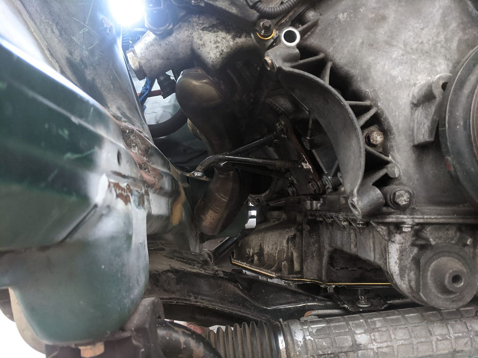
A look underneath

I also wanted to check clearance with sunken/worn engine mounts so I installed a worn pair I had on hand... trying to do it like any other BMW, just by raising each side... worked great
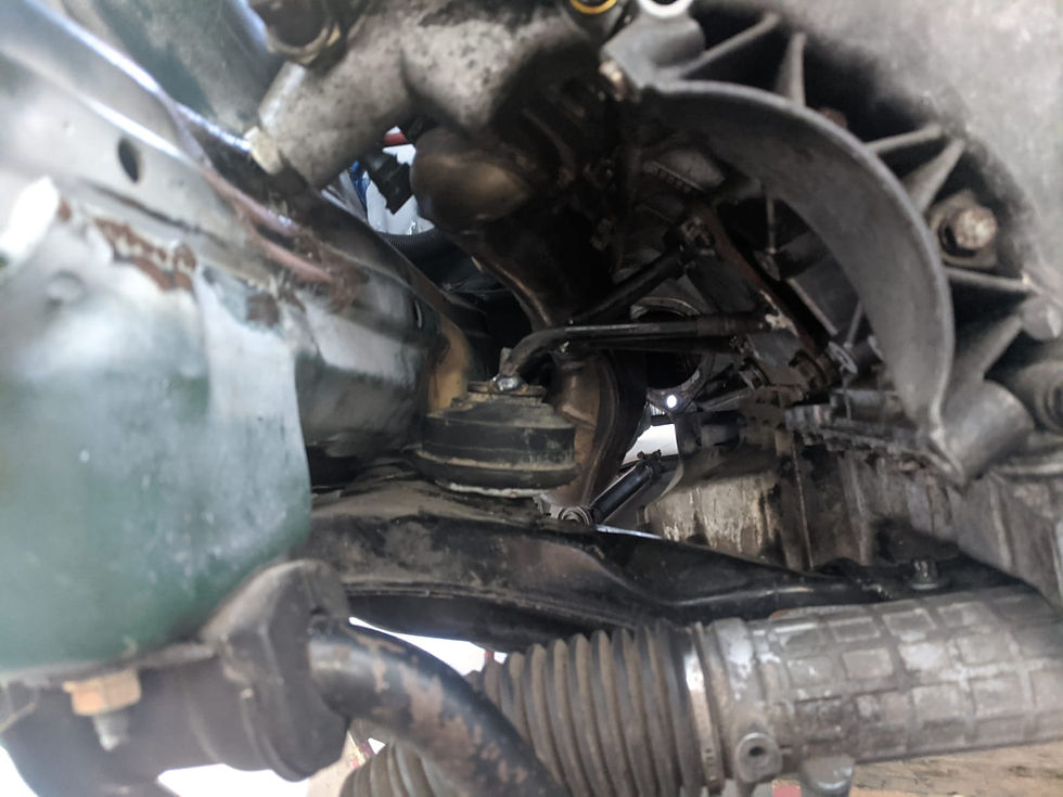
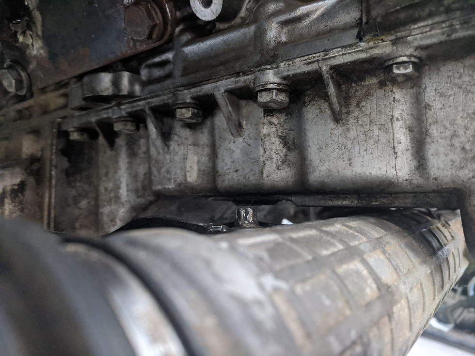
Clearance was tight but workable. The "rib" on the oil pan closest to the screen just over the steering rack was the tightest point, I may use my rotary tool to create a little notch where this could potentially rub
Once the original mounts were back in I also ended up raising the driver's side just a tad - it was lower than the other side, doing this also brought the flanges parallel and the bottom and the oil pan level with the x-brace. When the engine mounts are reinforced at some point, I will weld the washer into place onto the bottom of the engine mount

These are the angles of the engine using the swaybar as a reference for zero as I found that to be the best to get a consistent reading of a flat surface relative to the chassis
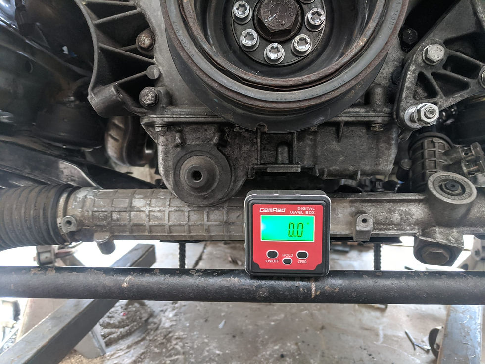


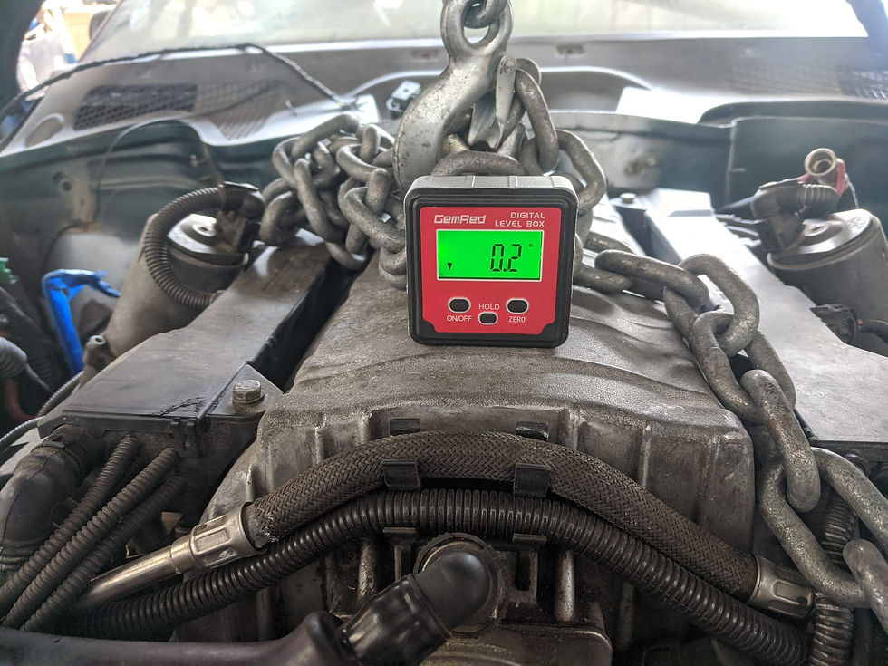
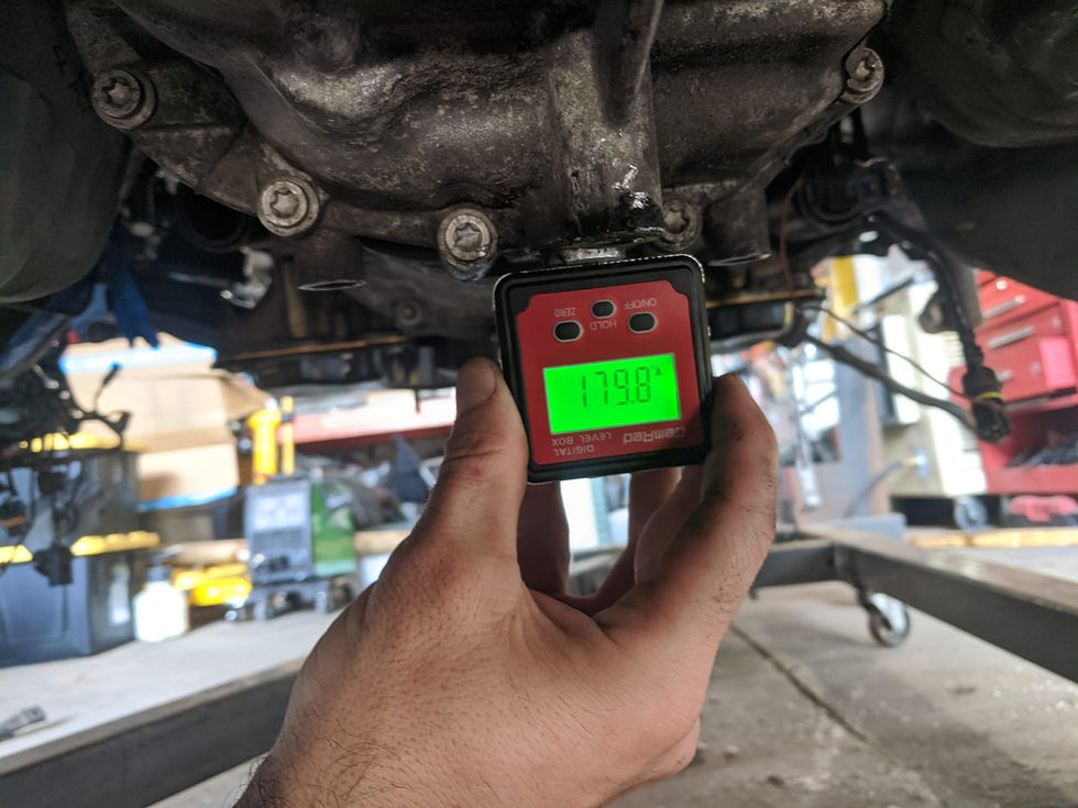
Engine (and trans...) seem to only be off by .2 degrees which is fairly insignificant, I re-checked with my laser tool and that looked good too so I think I am finally 100% done with trans/engine fitment
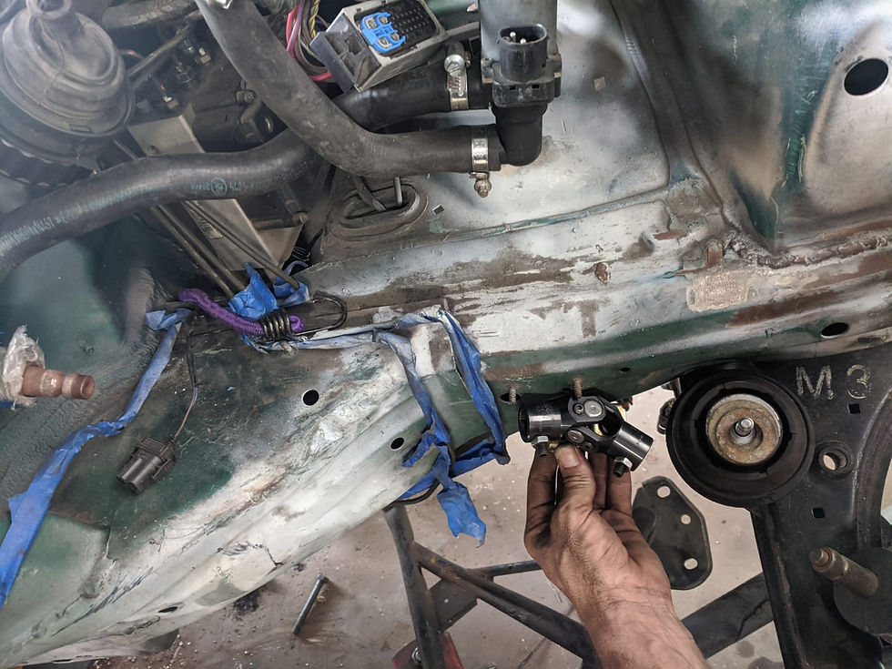
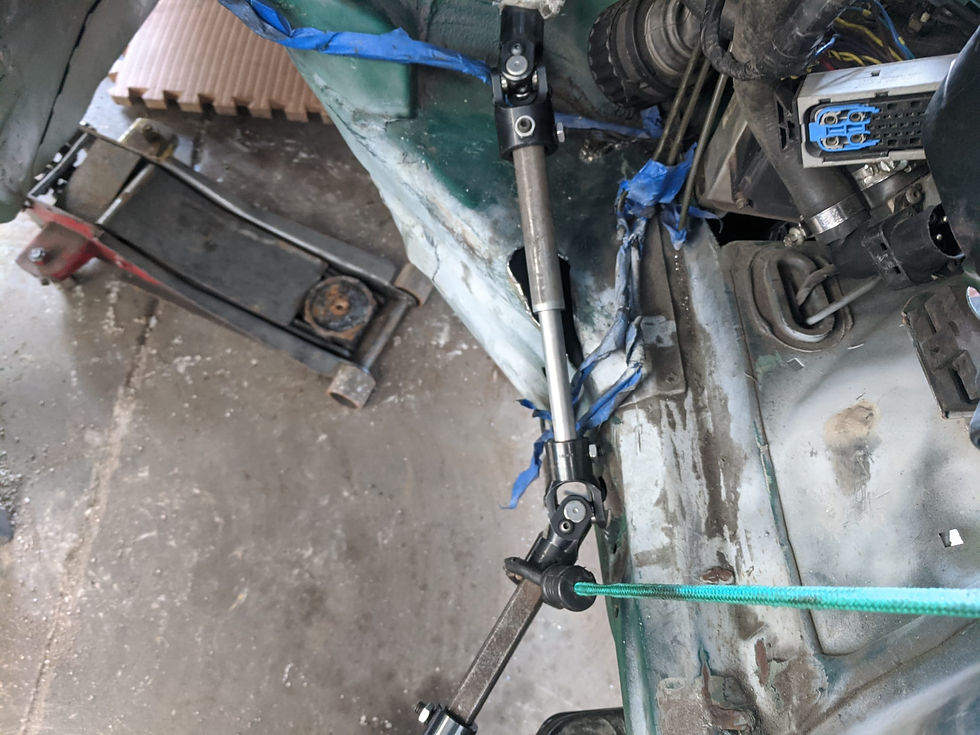
Mocking up the shaft... I had previously marked where I thought the U-joint should go so I started there and worked my way outwards
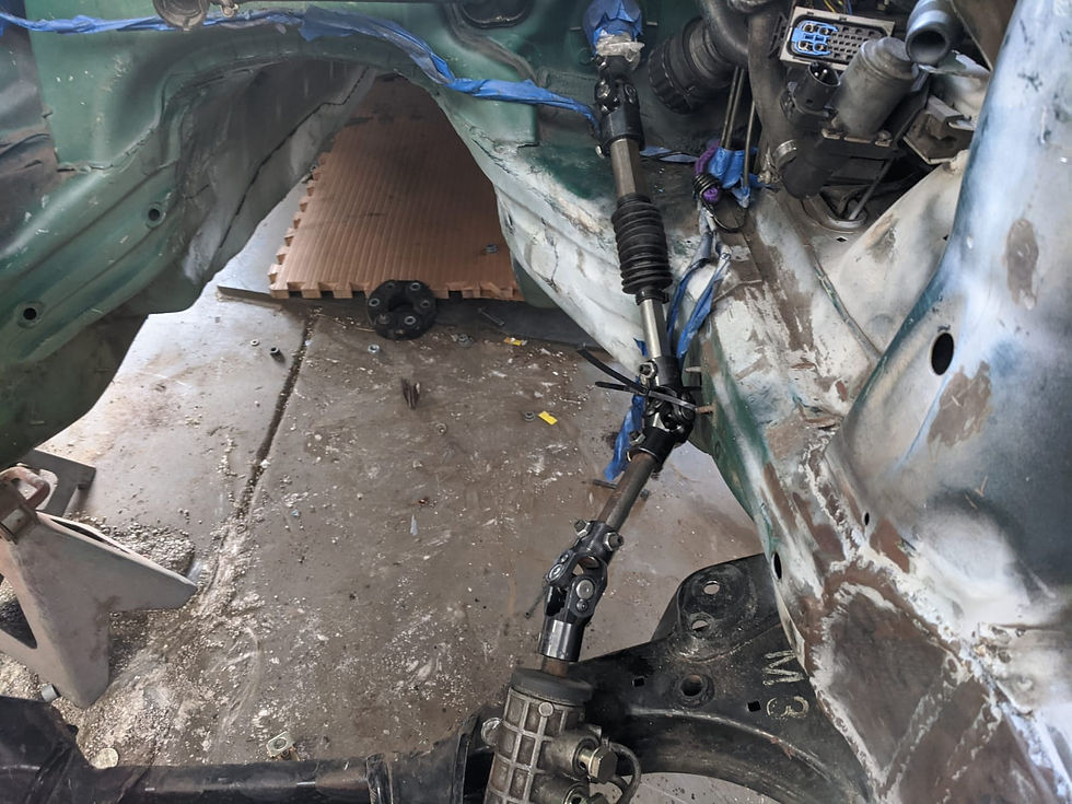
Once again using the power of extensions... I had an idea for a 3D printed contraption but ultimately decided it wasn't needed

Then I re-installed the engine...

Once I had deduced this was the routing, I went ahead and removed the engine again and then measured the extensions to get my rough measurements

I cut the pieces a little long to give me room to adjust a little bit here or a little bit there and then cut the shaft to size. The upper portion remains a collapsible shaft
Currently a ziptie is acting as the support bearing

Then once again installed the engine to see if this would actually fit...


From here it was good, but up top it was really close - basically hitting the headers. I already knew I was going to notch the framerail a bit to fit the upper shaft where I wanted it so I knew fitment would be a little worse than when installed but due to just how tight it is I decided at this point that I will also be notching the headers just a little bit where the clearance issue is just to make sure there aren't issues there down the line. The clearance at the engine mount side of things meanwhile looks fine
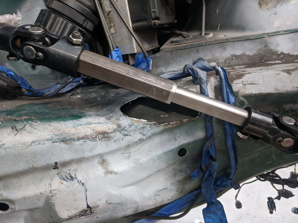
Time to start mocking things up. The shaft was hitting the chassis a little bit here, so I cut out the area around it and will eventually weld in a "pocket"

I was maybe a little generous with the cut but I may also adjust this a bit later so the upper bit sits a bit lower
Tack welded the support bearing in place after a lot of test fitting. It is sitting at a bit of an angle here, that was slightly reduced when I disassembled the shaft and screwed the bearing in, shortening the length and moving it "up" the rod, helping to straighten it in the process. I did find that it spins better at a slight angle, so I decided not to have it sit "straight"
This is about where it ended up. I clearanced the framerail with a hammer a little bit to allow the joints to rotate freely in this area

Next up was to get the engine in... for the first fit I installed it with worn mounts and no spacer on that side to get an idea how tight it'd be in a sort of "worst case" scenario. I don't see it flexing more than this even on worn engine mounts. Lower clearance is good, but the upper does need some further adjusting - likely I will simply notch the headers a little bit

Then with a new mount and the correct spacers back in... tight, but should be workable. The support bearing is in front of the header by a little bit too
The upper clearance by the header is much tighter... too tight...

There a couple ways to adjust this that I see but my original plan of lowering the linkage further will likely not be possible. Part of the reason is shown below with my very non-scientific way of measuring the operating angle
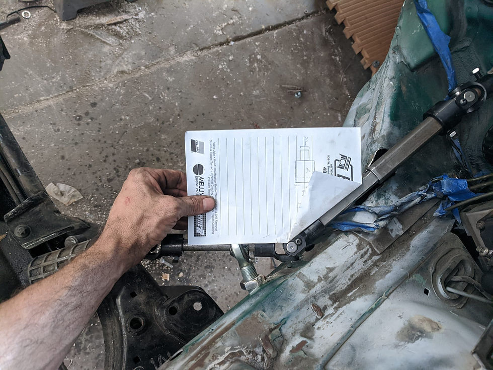
I then measured the paper and found the angle to be about 35 degrees depending on how I held everything... when I look at the picture and measure that, I get a hair over 35 degrees

In any case, where it is now, it feels good... it spins freely... but when I adjust it too much out from here, it does start to get weird and bind a little bit. I have maybe a few degrees of play here or there but this is essentially where it needs to be
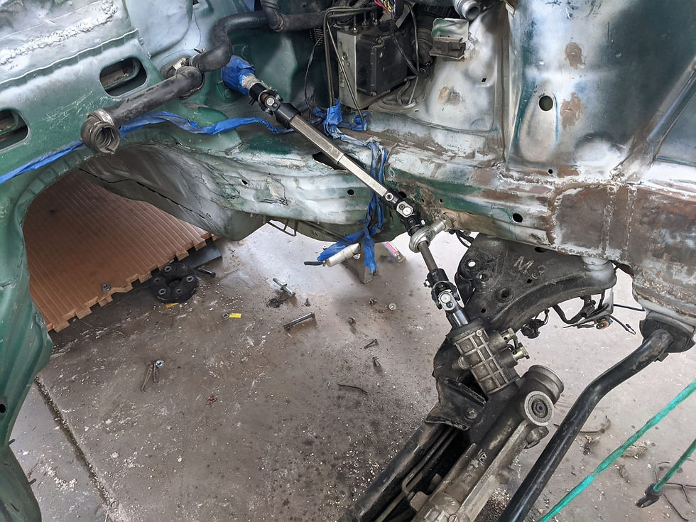
And with the engine in place...
I'm going to fiddle just a little bit to see if I can get it to have more clearance around the headers - there are a few ways I could possibly do that but I will likely end up, like most things on this project, basically splitting the difference and doing a little of everything. Including notching the headers. But for now it steers! It's just a matter of tweaking from here
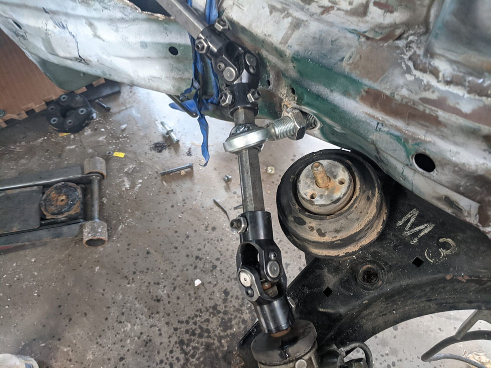
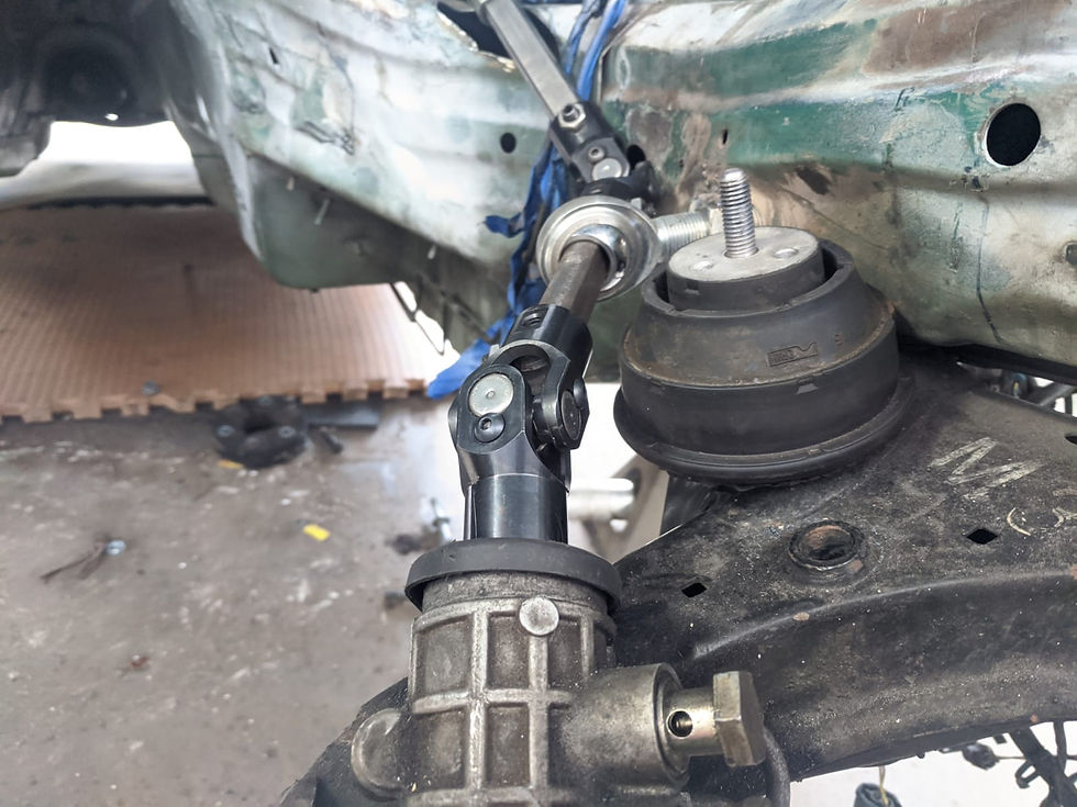
After some more consideration, I decided one of the tweaks I needed to do was one I anticipated earlier, which was to trim the input on the steering rack. This allowed me to move the U-joint down the splines further, which in turned lessened the operating angle of the center U-joint. I then ensured the upper U-joint was as deep on the splines as it could go, again to lessen the operating angle. This was all done so that I could then lower the center U-joint down the frame rail, which increases the operating angle - but because of the other changes, the operating angle remained workable

All the way down the rack... (this is not the rack I will use for the final build so I will have to repeat this process)

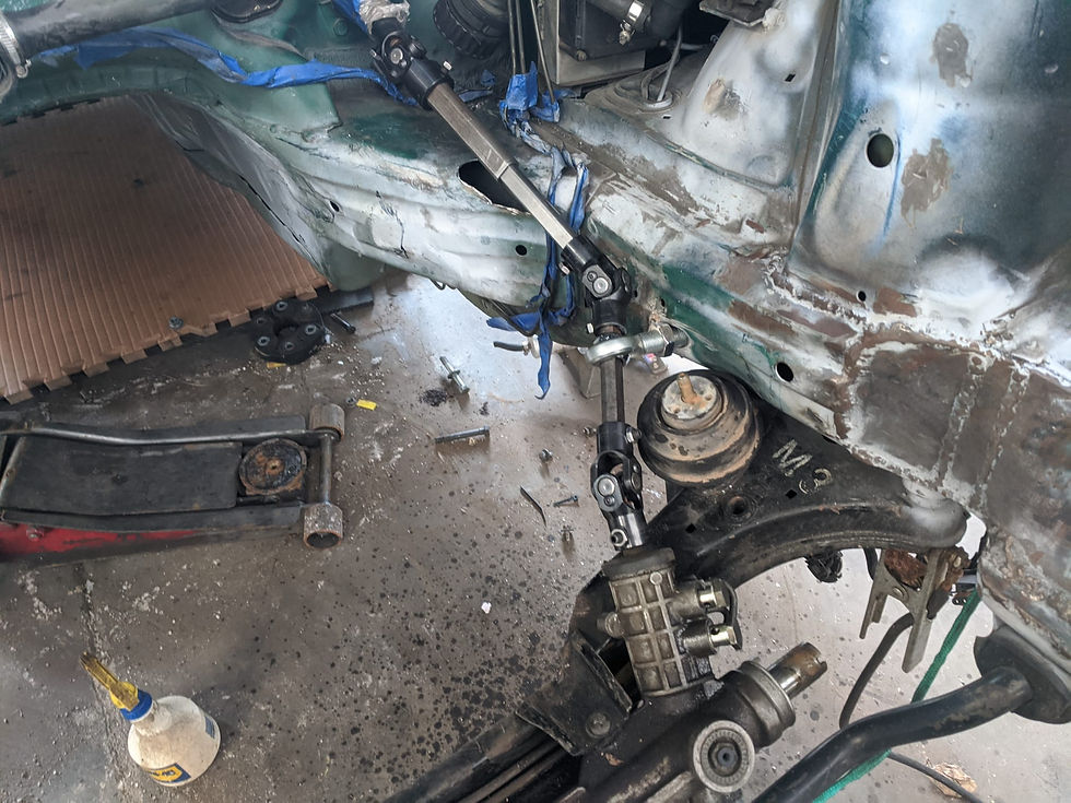
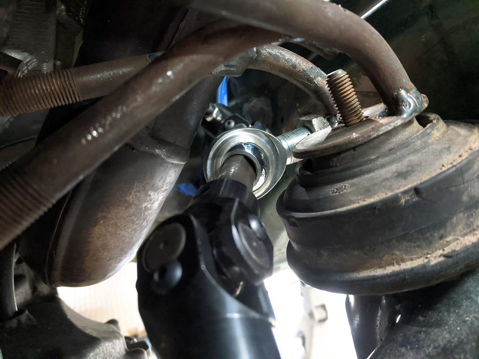
Upper U-joint all the way installed

Which allowed me to lower the shaft
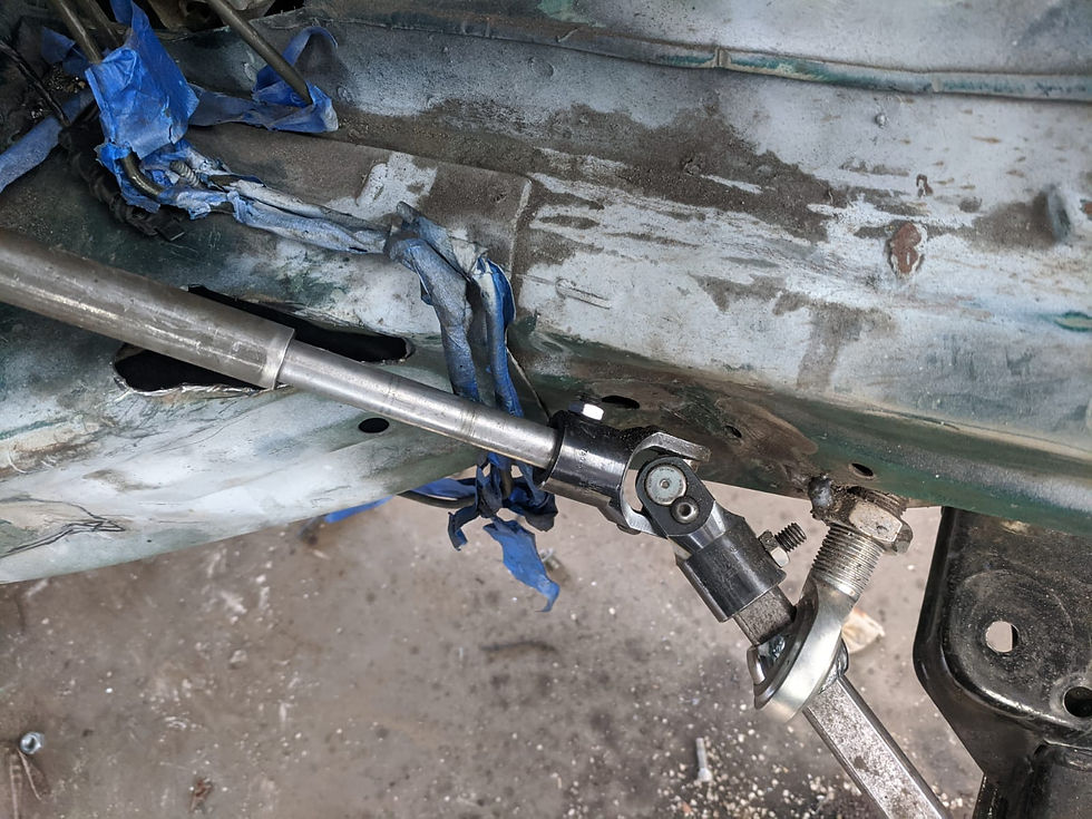
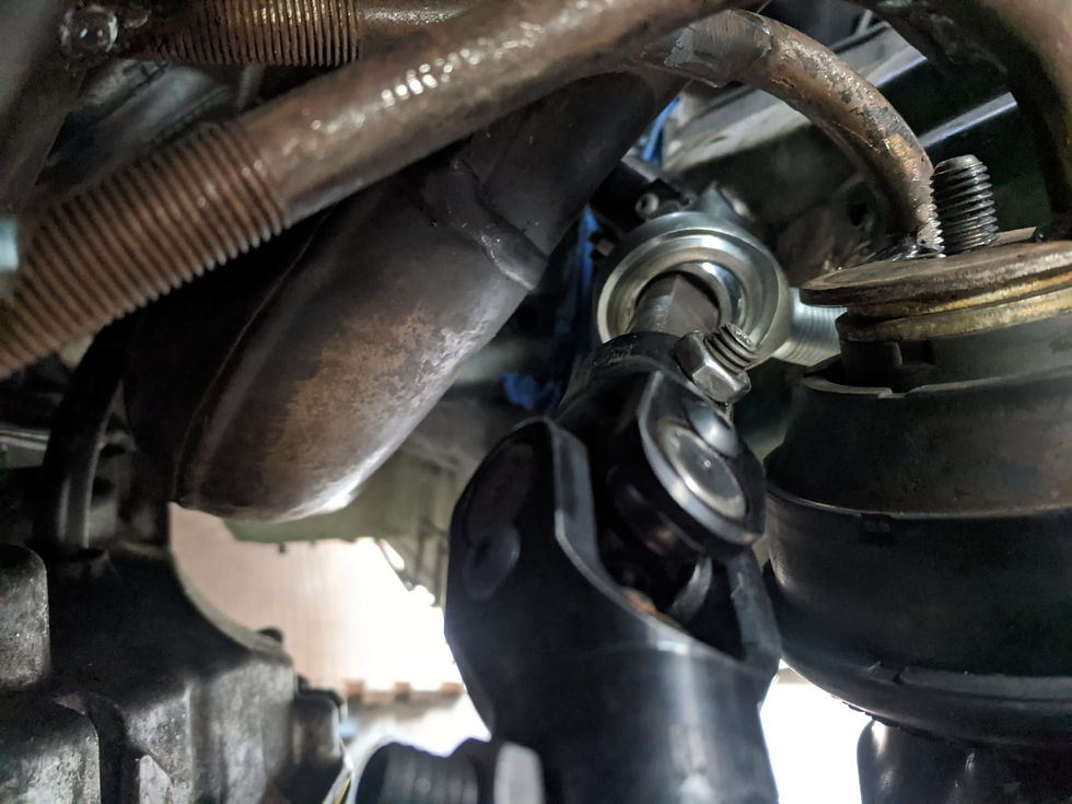
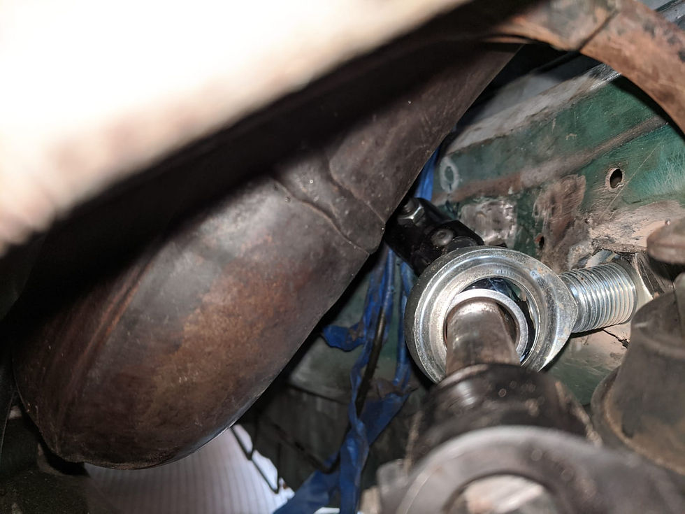
Still clears here, but with less angle at the center joint
Installed the brake booster to test fitment next time the engine is installed
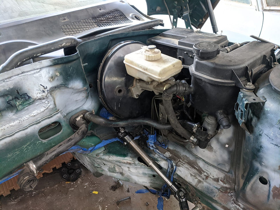
And it clears! Fitment is actually really good
This is the clearance with a worn sunken mount and no spacers
It clears up top - just barely, but it does clear

Clearance with the proper height engine mount with correct washers installed
Good clearance, not great but... good
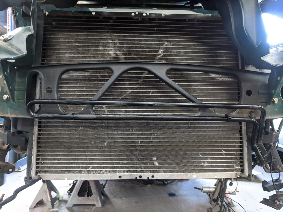
Next I just wanted to have a little fun and threw the rad support on, test fit the dual intake and looked at it with the beauty covers on

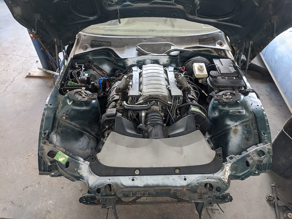
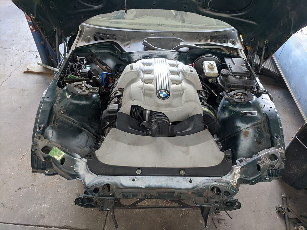
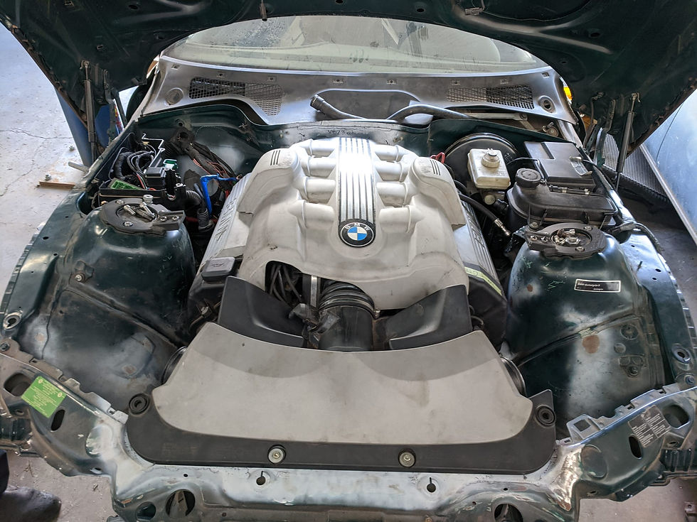
The real question, black or gray valve cover ...covers
Steering looks great though! I think it's just a matter of finalizing the support bearing location and welding a little shield around the upper shaft (just in case)
One more beauty shot for motivation...!

Next I focused a bit on the power steering stuff - it would have been fine to drive it without the power steering setup but I'd really like it to work as close to how I think BMW would have built it as possible...
First I installed what BMW calls the "suction hose" which is essentially the supply line from the reservoir to the pump - this is a stock hose from another BMW model, trimmed just a bit shorter. A lot of BMW models they run the P/S line behind the alternator from the factory and ultimately I decided to mirror this setup. I was originally going to run it in front but ultimately decided that for this hose at least, behind the alternator was better

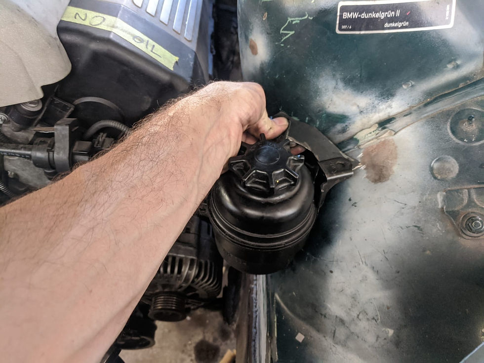
Up top it was in about this position. I'm using a stock power steering reservoir bracket flipped upside down

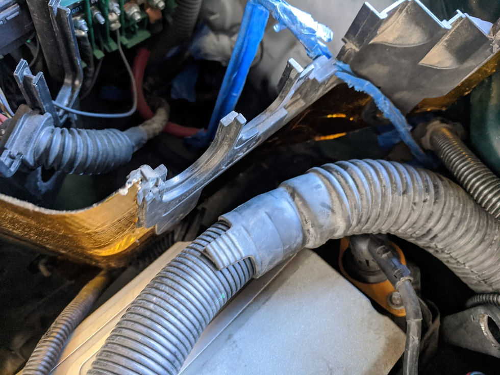
I started devising a plan and the first step was to trim off a bit of these ridges to allow for the bracket to lay flat
I then cut up a bracket with the help of some cardboard and started to mock it up in place
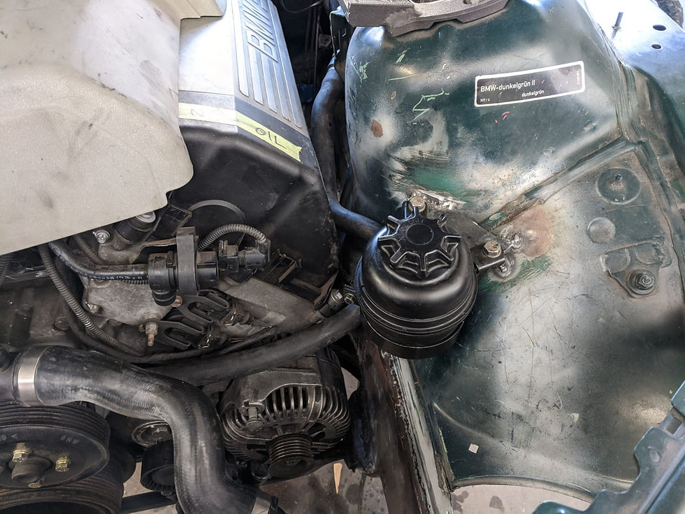
And installed! In hindsight I probably should have added a little "ear" to the bracket more like an OE bracket but this will work
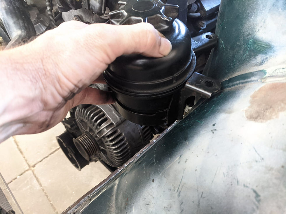
I did also spend a bit of time fiddling with E46 power steering cooler and the E46 radiator but ultimately decided I don't think I will use either of those in the final version of the build although I did note that the E46 power steering lines at the rack could likely be made to work due to their length. So I will likely modify my Z3 power steering cooler to have E46 quick-connect ends and then use a combination of hoses from BMW's with quick-connect attachments
This is the E46 power steering cooler ziptied in place to mock it up... while it does fit in that space reasonably well, I am pretty sure that space will be ultimately occupied by the aux fan
So the power steering stuff for the most part I have a plan for at this point, I just need to execute once I have the rest of the stuff in it's final position (including radiator core support and all fans as well as condenser and radiator)
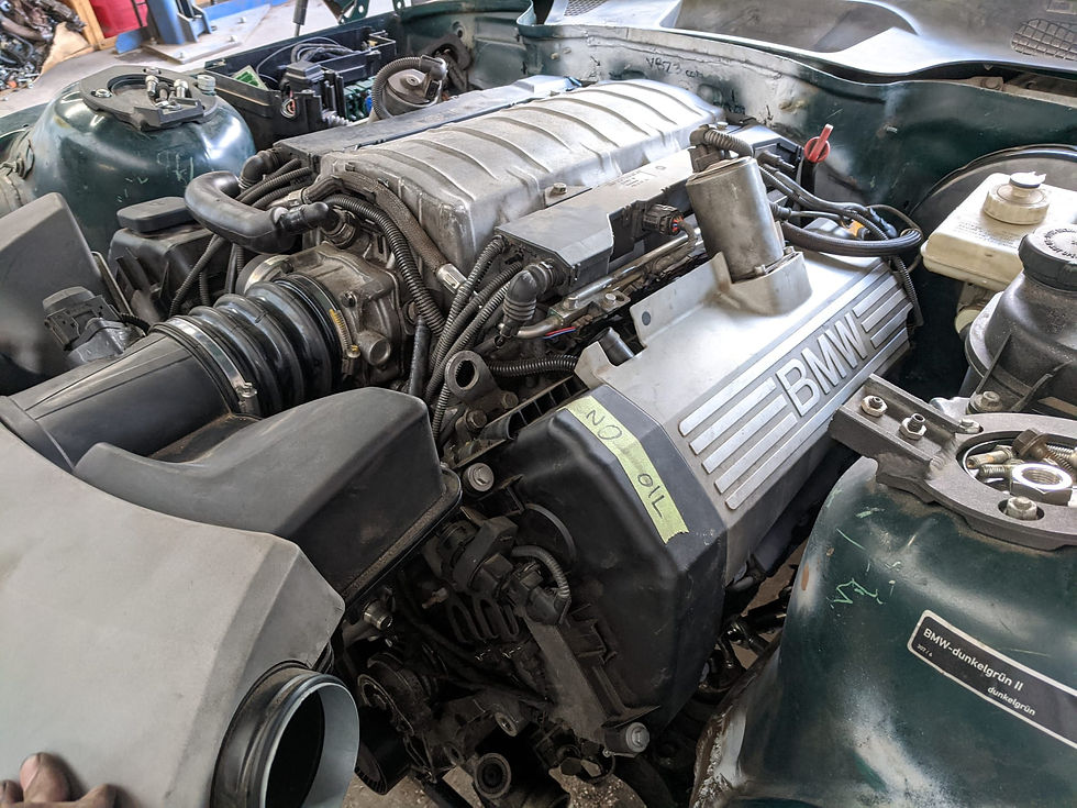
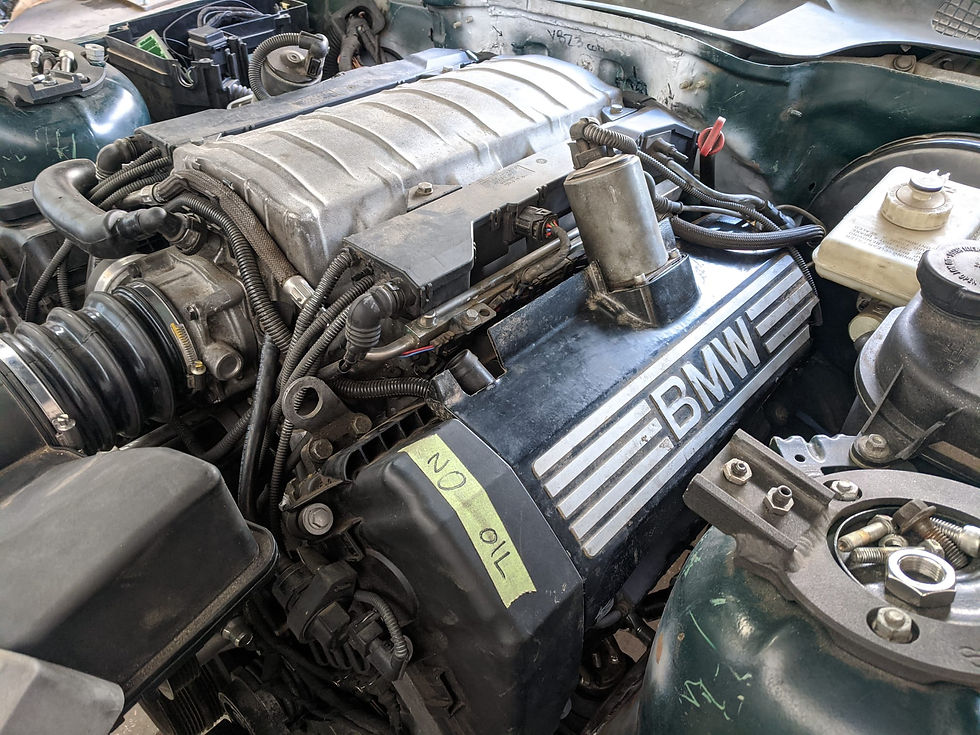
Speaking of radiators, still a little unsure what to do, the main issue is relating to having to make custom size/shaped hoses to fit the quick-connect engine connections but with the older-style normal "barbs" on the Z3 radiator. I will likely end up running it like below with the lower hose temp sensor connected to the thermostat/water pump but am looking into other options as this isn't my first choice of how to do it

The lower hose temp sensor (the left most sensor, unplugged) should be as close to the cold outlet of the radiator as possible, on factory applications it is built into the quick-connect hose that plugs right into the radiator. The middle electrical connection in the above image is the electronically controlled thermostat and the far right is another coolant temp sensor. I am not entirely sure the effect of running the outlet sensor so close to the thermostat, I need to do more research on that
I also go a little distracted and wrapped the DME area cover in gold reflective tape and installed it. I later cleaned up the edge a little bit where the gold tape stops
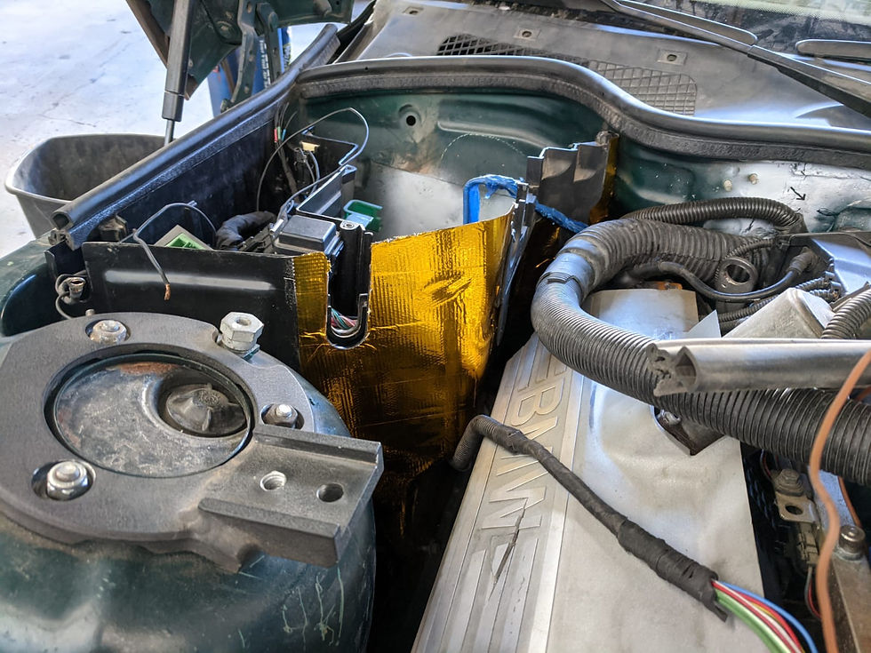
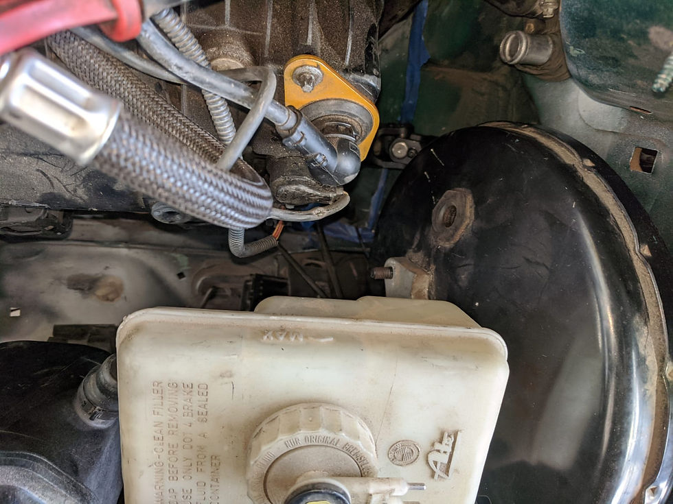
Then I got started plugging some things in... I wanted to make sure that everything would still plug in since stuff had been relocated. It ends up with the ABS module plugged in, the round diagnostic port does not fit in the stock location. So this led me on a little tangent...
I first relocated the round diagnostic port here - one side clipped in, I will plastic weld the other side of the clip into place here. Tight against the booster but it fits

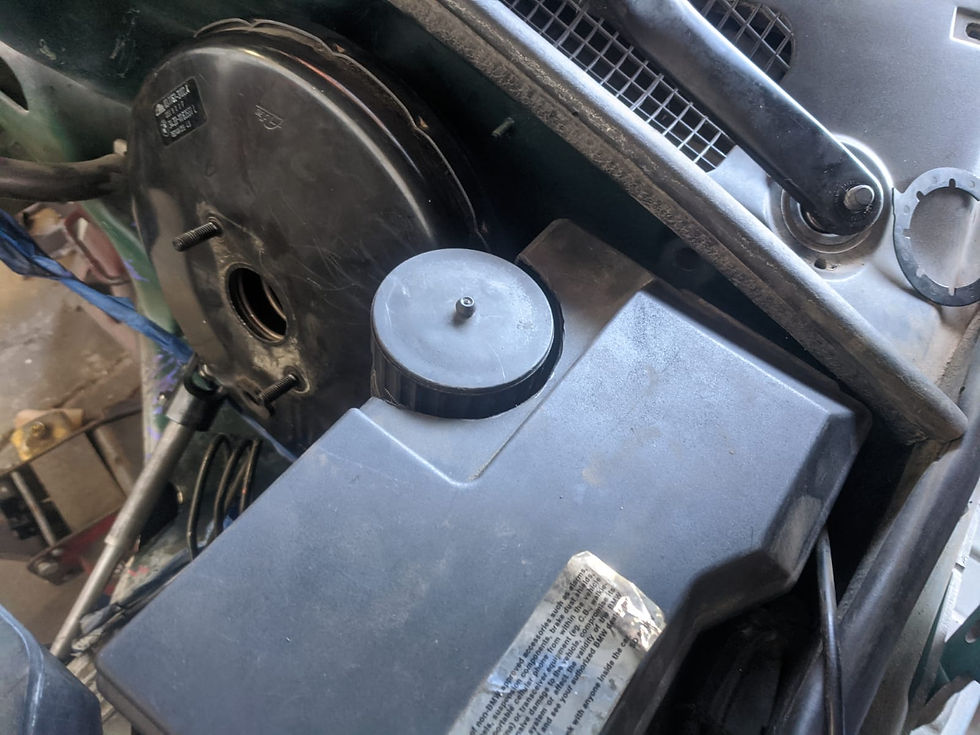
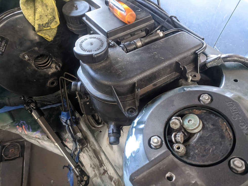
Then I wanted to cut the bracket off that held on the round diagnostic port since it wont be in that location anymore. Because I was doing that, I thought I should also move the expansion tank over a smidge. It was pretty tight when the engine was going in and the valve cover got caught on the hoses coming off the expansion tank a few times so I am hoping this will provide enough clearance that wont happen anymore
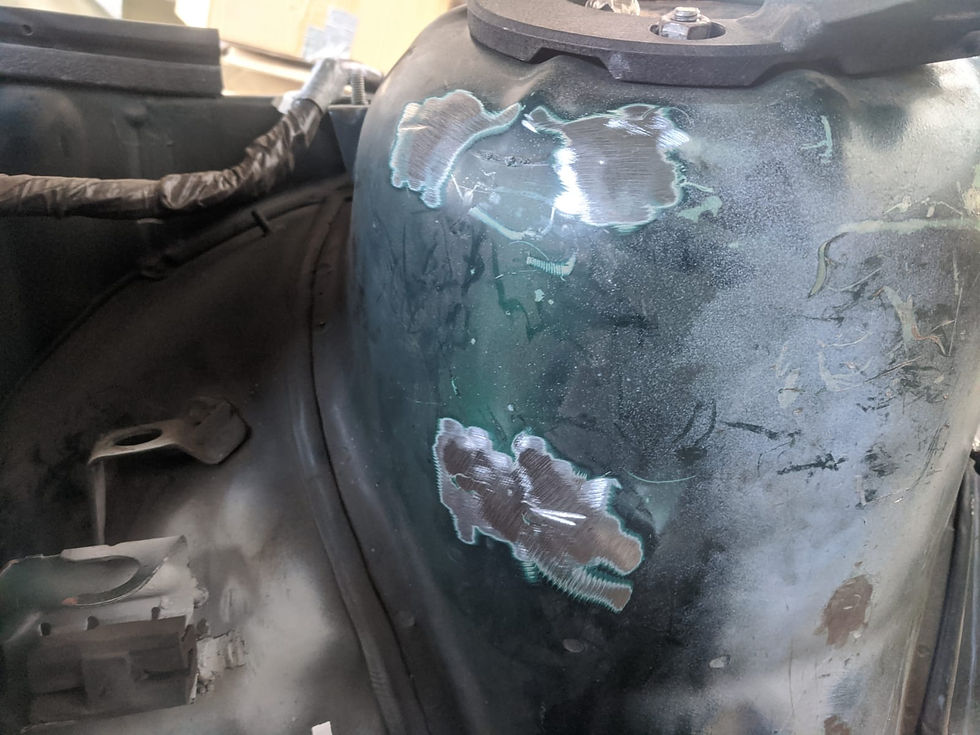
Pretty clean cut although gouged into the metal a tad on the lower bit
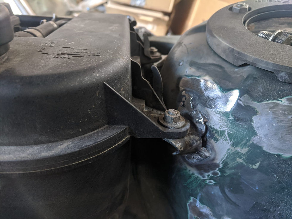
I didn't move it over much... I was test fitting it with the stock bracket in place on the right and the final placement ended up just a bit over from here
I'm not gonna lie, my nozzle on the welder broke and I don't have any spares so I ended up just doing these brackets without a nozzle so there is a little wandering of the arc but honestly, it wasn't too bad
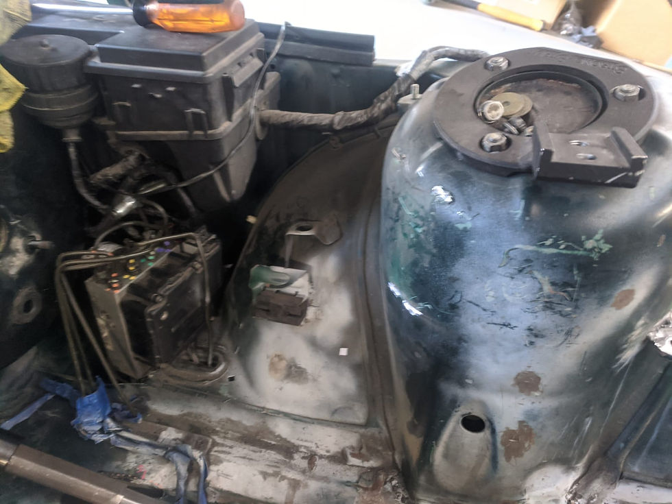
Plugged everything in then took a look, the clearance on this side of the engine bay looks much better now despite these being small changes


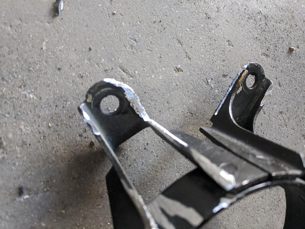
I also took the time to drill the recesses for the set screws on the steering shaft. Pretty simple process just mark with a punch and drill to a reasonable depth

Test fit with the set screws in place. I may drill some of the recesses a bit deeper after test fitting but it still fit which was the most important thing

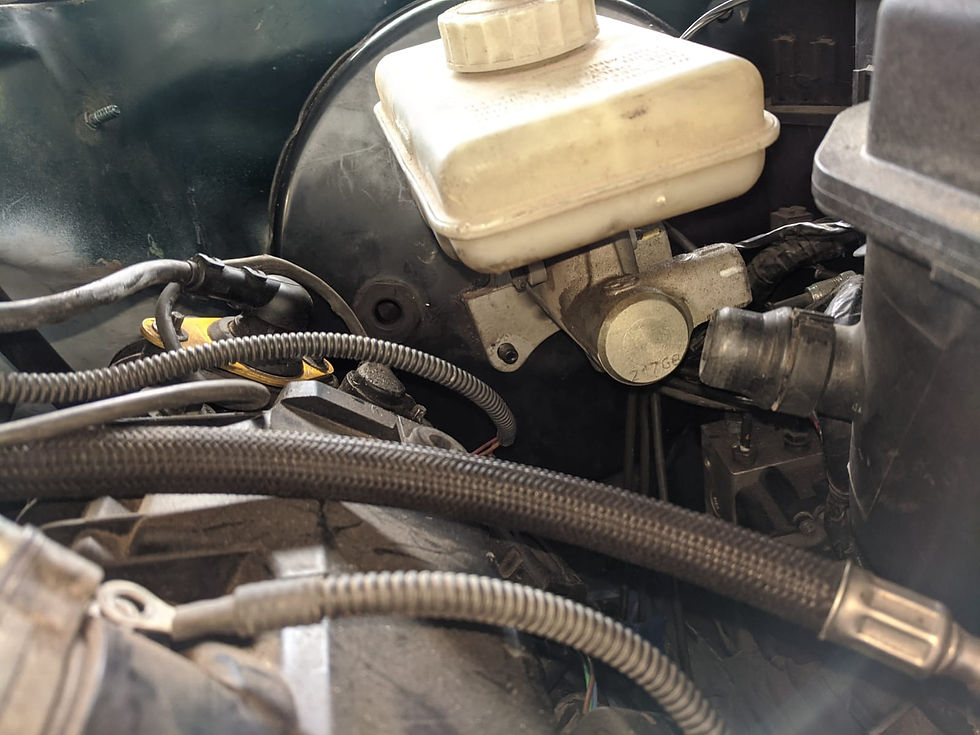
At some point during the day I also marked the brake lines with a paint pen. The front lines were marked at their end points and the rear lines were marked roughly in the middle and at the unit. These lines pretty much all need to be re-bent to allow the master to sit here. That includes the ones I made way, way earlier in the process but it should also yield a nicer looking end product. I have a fancy flaring tool which should have the correct flares for the BMW master cylinder. I will likely re-run both front lines end to end but splice into both rears using a double flare union

The only thing that doesn't have a bracket yet is the ABS unit and I am not sure I will be able to get the bracket for it in place. If I do - I don't think anyone would notice if I have to splash a little touch-up paint back there...

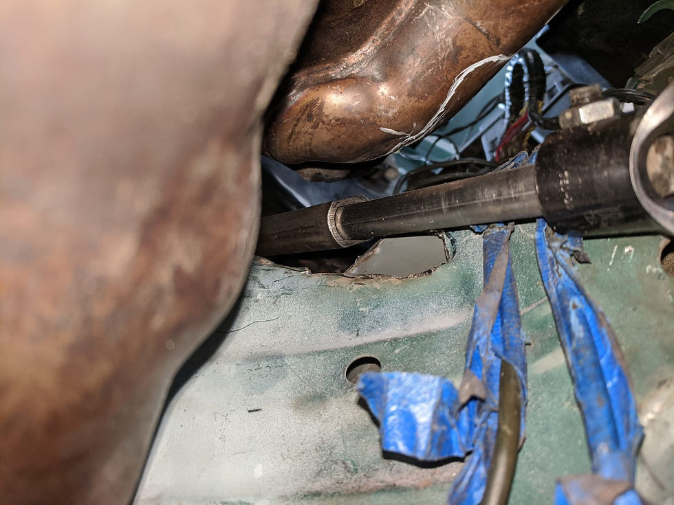
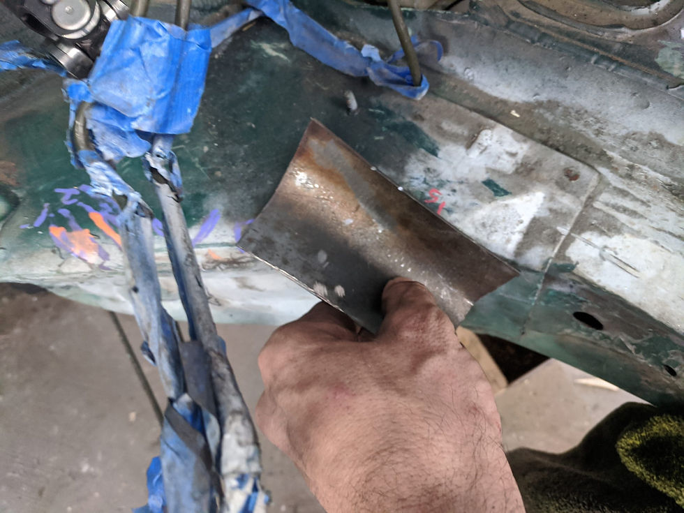
There were a couple more things to work on before I could get to paint prep and that was to finish the "pocket" for the shaft. I initially planned on hammering a piece of steel around my jack handle to form it to shape but that didn't work at all. I improvised something in my press and it actually resulted in a very nice, uniform round bend (though the forward edge of the piece wasn't cut perfectly straight so it didn't look amazing in the below picture in hindsight)

Test fit in place, its hard to get an idea of the depth here but this is a little "pocket" for the shaft to sit into
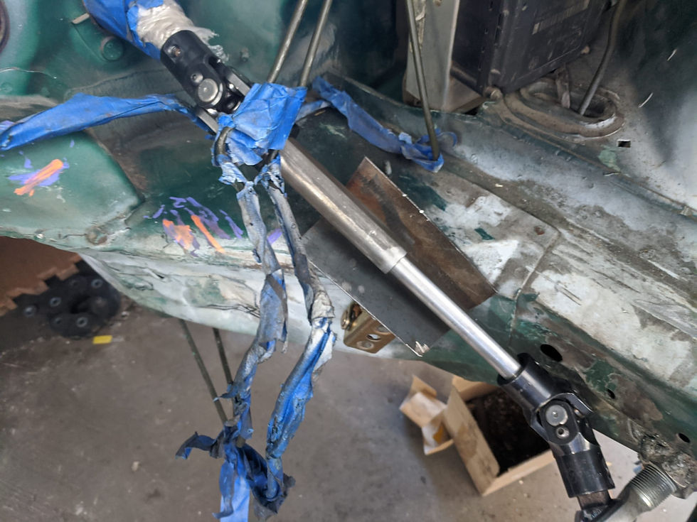
Marked it, cut it in small increments until it was a snug fit then welded it in place (the shaft was off when welding, this was just after test fitting it again). I did blow a hole in the forward edge which was a bit of a bummer, it was pretty ugly getting it patched back up on what was up until then a nice looking job

I also realized there was a bracket I don't need on the passenger side strut tower so I cut it out

Getting closer to paint...

I think this is a bit too long at this point for one post as well and the main focus now is past the steering shaft so... Part 20


Comments